
It has been about a year since I described the last resin freight car kit builds. A number of other layout tasks have commanded my attention, including a recent operating session. But there have been a few kit completions in the last few months, including a wonderful resin box car kit that includes etched metal and laser cut wood detail parts. Yarmouth Model Work introduced this kit earlier in 2014 and I scooped one up as it fits my 1926 era. Era appropriate decals even came with the kit! The completed model can be seen in the image above. Click on any image here to review a larger size.

March to July 2014
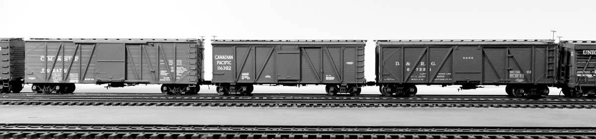
Yarmouth Model Works Northern Pacific double sheathed box car
Funaro & Camerlengo PRR GR composite gondolas
Here we are at the end of July 2014 and I’ve only tackled three resin freight car kits this year. The layout has received a great deal of attention but it can always use a few more freight cars. Here are the latest builds.
Northern Pacific 40-foot, double sheathed box car with fish belly center sill and truss rods
I started this Yarmouth Model Works resin kit as part of a group build with the resinfreightcars YahooGroup. The model reflects a Northern Pacific double sheathed, truss rod, 40-foot box car prototype. 4000 of these box cars were acquired in the 1912-14 time frame and many ran into the 1960s with upgrade AB brake systems or in maintenance service.
The original cars were delivered in the 21500-23999 and the 39500-40999 series. Here’s a prototype image of a very similar Northern Pacific box car along the DL&W in 1918, but this car seems to lack a steel center sill.
The underframe detail proceeded smoothly, but there are a couple of points to be aware of. If you plan to run the air line from the K brake dirt collector through the center sill and over to the air line, I recommend drilling the hole through the center sill before installing the truss rods/queen posts and needle beams. These parts will be in the way if you plan to model the airline connection and want to drill through the centersill. I drilled at an angle into both sides of the center sill just above the bottom flange in order to mount the wire pieces to represent the connection that passes through the centersill.
Here’s another tip for those building the NP car. When you clean the flash, open the slot in the centersill for the brake lever. I missed this when I started and discovered the need for an open slot on the first evening of this build. After discovering this, I just closed up for the night which gave me time to think through the situation. I used a #73 drill bit to open the slot as it was just long enough to keep the Dremel tool chuck from hitting the model.
Once the truss rod details are in place the brake system components are installed. Several of these are etched metal parts and are the bees knees! A set of fine, curved scissors from the drug store make-up aisle is used to remove the etched parts. The A-leg etched parts are delicate and do not hold up to repeated bending at the joints when working to establish the proper lever levels. One leg separated from a unit but a dab of Barge contact cement mended the joint enough for installation. All bends received a bit of cyano acrylate (CA) once they were installed.
The underframe has many fiddly components that present a very high level of detail when finished. A couple of times I worked for an extended period only to find I did something wrong. Rather than push onward, I stepped away from the work and did something else. In one case, it was late so I went to bed. When I returned to the problem parts, my mind was refreshed and I easily determined a quick and effective fix.
I don’t usually add this much brake system detail on my models, but I wanted to push my skills along and add as much detail as suggested by the instructions. Here’s the completed underframe.

After the underframe detail, attention turned to installing grab irons. All grabs are non-standard and were bent to fit. The side ladders are about 24 inch width while the end ladder grabs are about 12 inch width. The bottom grabs on each ladder are half drop; one leg straight and one leg drop. I installed those after carefully straightening and rebending one leg of some drop grabs.
After installing the running boards it was time to modify the trucks. This is one of the more interesting steps in a freight car build. I do not recall anything quite like this. The side frames of Kadee Andrews trucks were modified then reassembled. The prototype had an odd inverse arch on the side frame, so a cut must be made with a Dremel cutting wheel on the underside of the side frame chord. The side frames were spiked to a wood slab to minimize movement. I got through most of the material on one side then flipped these over to complete the job. The top chord will now be squashed down and glued. I did mash one sideframe beyond use so be gently with steady pressure on this step. The kind folks at Kadee sent along some replacement side frames at a nominal cost.
Here are a few images to illustrate the truck sideframe modification steps.


The sill steps and the vertical brake shaft were the last details installed. The sill steps are installed by hanging the etched metal parts from wire pins mounted on the lower inches of the car side. The instructions recommended specific locations to drill for the sill steps so I made a small jig from styrene scraps to assist with the holes. This worked very well but I found the half drop grabs at the bottom of the ladders interfered with easy installation of the sill steps. I would recommend installing the half drop grabs after the sill steps. There are only two of those grabs and they can be bent to fit with the other grabs, just installed after the sill steps. Here’s a close up of that location.

So another HO scale resin freight car is built and ready for the paint shop. This is one of the most detailed cars that I have built and I enjoyed working on it. There were a few frustrating steps, but I learned how to work through the challenges. I can hardly wait to paint and letter this little beauty.

Pennsylvania Railroad GR class gondola
Looking back through my image archive, I started building two Funaro & Camerlengo Pennsylvania Railroad GR class gondolas in the last week of January 2014.

The Pennsylvania Railroad built thousands of gondolas with fish belly steel side sills, steel side stakes, and wood sides. These were split into two car classes.
GR – 16,151 built 1902-1907
GRa – 14,126 built 1907-1916
With these kinds of quantities, anyone modeling the era between 1910 and 1950 will need a few GR/GRa gondolas for their freight car fleet. These F&C kits are a nice introduction to resin kit building and they are great steam era freight car fleet additions.
Before starting the build, I thought I should scribe the board lines in the back if the side castings. An eight inch wide piece of styrene helped in setting these lines. While scribing I noticed the sharp blade was going though the casting. This inspired some creativity to distress the wood parts before building the model. Here are the parts after a little work. Yes, those are holes in a couple of spots. A wire wheel in a motor tool worked to scallop the top edge. Speed was on low, of course. You can see an outer and inner view in the image.

The inside surfaces were brushed with a file card and washed again. An oil-based burnt umber wash was applied to the wood components in hopes that a light overcoat of freight car color will show a little contrast between the wood and metal parts. Contact cement was used to attach the initial installation of the sides, ends, and underframe. Once these parts are together with the contact cement, then I hit all the seams with thin super glue.
Couplers and trucks are installed, and attention focused on the ends. The F&C directions recommend an angle piece at the base of the drop ends but that was when steel plate doors were installed during fleet upgrades. I’m glad I reviewed a couple of prototype images before installing the drop ends! I removed the rivet detail and scribed board lines on the end doors before installing. A slab of styrene was added on top of the sill to reflect the practices seen on a pre-Depression era photograph. Next, a motor tool was used to drill the holes for grab irons, sill steps, and towing staples. Each corner of each car received the same hardware as seen on this image.

These gondolas assemble quickly and have just enough detail. I used sheet lead under the cast wood floor piece to add weight to the model. Tahoe AC&F arch bar trucks were used to reflect the pre-Depression era hardware. Once these are painted, Carmer uncoupling levers and vertical brake staffs will be installed along with air hoses. These cars have already been used in a couple of operating sessions of the Wheeling Freight Terminal. I started these in late January and had them ready to use by late February.
Here are the pair of GR gondolas in contrast with an Intermountain USRA composite gondola. This image was taken before the grabs irons were installed.

Thanks for stopping by. I’m up to my elbows in four more resin kits builds that will be featured here soon. Your questions and comments can be posted below. All comments are reviewed and approved before they appear.
Thanks for posting the construction hints for resin kits. Great to see that someone else models 1926 besides me (SP in northern CA). Will have to explore the rest of your web site soon.
Have so many Westerfield kits to assemble, but have been busy with layout scenery and getting ready for my first op session.
Take care,
Gary
Thanks for stopping by, Gary! I enjoy sharing build tips to encourage others to open the box and move something along. I hope you find additional blog details helpful to your modeling efforts. – Eric
Eric,
Cars are looking good. I’ve been in the process of finishing up some “half started” resin cars. They’re just about done now, and my next projects are going to be a couple of the Yarmouth cars. Thanks for the tips!
Marty
Thanks, Marty! You reminded me of a B&O box car resin kit that is lacking three sill steps in order to be complete. I know it’s here somewhere.
Good luck on the Yarmouth kits. These are really sweet builds. – Eric
Eric,
Nice job on that NP box. Your comments on the various assemblies mirror what I encountered in assembling my kit. However I elected not to model the train line, I did “modernize” mine with AB brakes to fit my modeling era. This also meant I did not have to fuss with that truck modification.
You are correct in your assessment of when to mount the bottom sill steps. I made my bottom ladder steps from straight wire and mounted them, then had a difficult time, later, of mounting the sill steps correctly. I found the underbody detail work to be a little fussy and time consuming, but not difficult This kit truly builds into an outstanding model and is worth the extra time invested.
I recently saw a photo of a B&O Seley hopper car which had those modified Andrews trucks. I think you could model this car using the F&C Southern kit and fit it with the above modified trucks. This car was one of the later acquisition Seley hoppers that the B&O inherited from a coal company (late teens, I think) and which ran into the ’30s.
And, speaking of time consuming kit builds, I am now working on three Sunshine GATC radial rivet tank cars. My main mistake was following the kit instruction build sequence. I’m having a devil of a time fitting the tank band anchor assemblies in between all the brake rigging. In order to get the bands tight, I have to solder wire to to the band ends and then epoxy the wire to the anchors. I can only do one band anchor at a time and there are 24 of them to do. It is tedious and slow, but not too difficult. Another good kit to walk away from at times, but worth the effort.
Will post photos when completed.
Jim
Hey Jim!
Thanks for stopping by. I put more effort into the Yarmouth box car than most builds as there was a greater level of detail supplied than usual. I figured I’d just push myself and learn a few things along the way. I’m glad I did.
I’m not certain I will tackle a GATX tank car kit, tho… But I do have a couple of those F&C Seley hoppers here.
– Eric
Nice work Eric. As it happens I too am in the process this week of finishing up two Funaro & Camerlengo gondolas I started years ago myself. Mine are a pair of D&H cars as opposed to your PRR. I finished one tonight and will decal and weather the other later this week. It’s good to get old projects off the shelf and onto the layout!
Thanks, Craig! Wrap up those D&H builds and send a few images and some build notes to my email address. I enjoy sharing the work of other modelers here, especially those firmly rooted in a pre-Depression Era. – Eric
Great job Eric, really appreciate your help and guidance on the kits. Hopefully I’ll get started on my battleship gons soon and get a build progress report of my own going soon.
Your friend from East Texas
Rob Dove
Thanks for the comment, Rob. I enjoy sharing the build summaries and photos. They are meant to encourage modelers to open those boxes and start building something. Opening the box and reading the directions is the first big step. It’s important to read the directions through once, then read them a second time and write down a build outline to guide your work. Dividing up the build into different stages or steps eases your work and understanding of the kit. You will find a few kits that are just plain tough, but most any build can be broken down into a series of smaller construction steps that push the work along. Feel free to send any questions my way via email, too. But the important thing is to open the box and begin! – Eric