
Repost: from January 2011
Over the years I’ve assisted with several model railroad designs and worked on the construction end, too. These have been for friends, a model railroad club and for myself. In almost every instance there is one constant through the design and build steps of each project. Believe it or not, whatever is on the paper may not fit properly or look right when the track starts to be installed. Really, I’m not joking. No matter how many measurements were taken, data compiled, and fussing done over the details for the design, it all comes down to the full size build with the form and fit. It is one of the most thrilling and disappointing moments of building a model railroad. And that is where I am right now.
Benchwork for the Newburgh layout has been mostly completed for a few months now. I had been fretting over how to cut out the subroadbed and be certain the tracks would fit properly. After all, there are seven crossings and six turnouts in a pretty tight space. I had previously worked to create a couple of scale drawings with paper and pencil, and I have completed transferring most of the important components into an electronic file using Adobe Illustrator. Below is a portion of the completed plan.

I decided to cut a slab of plywood to layout the track centers and be certain the design would fit and look proper. A large piece of luan ply was cut so all crossings would be on one piece and there would be no subroadbed joints to cause worry. A few of the tangent tracks were plotted and pencil lines drawn onto the luan ply. I also scanned the turnouts and printed those out to use in the process. Central Valley turnout kits will be used and I found it easier to employ paper printouts of the turnout ties than to use the actual product. The paper turnouts enable easier matching for crossovers by taping together at the overlap. Centerlines were also added to the paper turnouts, which made for easier placement with the pencil lines on the plywood. Here are a few paper turnouts taped together along the Newburgh & South Shore portion of the layout.

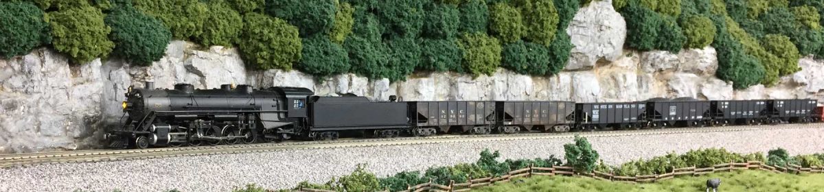
So far I’ve been excited with how the track components fit. Several sections of flex track were taped down. A loco and some freight cars were positioned to give a better feel for the layout. The train sits on the N&SS mainline while the track at left is the W&LE that sneaks off to staging at the bottom of the image.

Using real size planning has additional benefits over scale drawings with pencil and paper, or electronic graphic designs. Rather than use the common two-inch track center separation for HO layout, I decided to follow a more prototypical distance of 13 scale feet between parallel tangent main and passing track centers, and 16 feet for track centers between main and parallel tangent industrial tracks. A timely article on planning concentric curves with easements appeared in the 2011 Model Railroad Planning and offered additional help for several areas with concentric curves. For me, it has been much easier doing these fine adjustments in the full-scale application as track centers are drawn onto the plywood subroadbed. I’ve also been able to change a critical turnout to a gentler angle turnout and not lose any operational aspects.I do not want to imply the work on the original scale drawings and electronic graphic designs were not needed. Take this as a point of information as your layout develops that it is easier to fine-tune elements of your design in the full-scale size. The work done with the scale drawings certainly helped understand the possibilities of the space and I would not be this far along if I had skipped that step altogether to just plunk track components down and see what works. Each step in the process can enhance your efforts and help to build a lasting project. Establishing a firm starting point is essential for everything else to fall into place.

So that’s were I am on the Newburgh layout. I plan to mock up the crossings next just to see how it looks. Almost all of the track centerlines have been drawn for that portion and it also looks good. Adding track and maybe a few freight cars will help determine if any tweaks are required. Besides, it is very cold here right now and I really can’t cut the subroadbed until it warms up a little. Such is life with no real basement and an unheated garage. The last time I worked in the garage it was a bit too cold for my tastes, so I’ll wait a few days and hope for temps in the upper 20s! I’m sure my friend in Arizona will rib me for this.
Feel free to leave a comment. All comments are reviewed and approved before appearing here.
That is a very complex track arrangement. Can you allocate it to a bigger space or perhaps simplify it?
Thanks for stopping by Bernie! I do hope to rebuild this and I hope it will be in a room larger than the original 11×11 foot space. No track was laid before the recent move so the plan can be altered when I get to that moment again. I’m trying to repost severl of the original psotings to illustrate the prototype area as well. You are correct that it is a complex track arrangement, but that is what the prototype was like with three railroads crossing at grade. I can’t even imaging the original PRR traffic on their busy C&P mainline through here and trying to squeeze a W&LE or N&SS freight through the interlocking. Model wise, the PRR tracks are just scenery and not operational. Even in a future, larger space, I’d rather focus on the two smaller lines and their traffic density than attempt the PRR.
– Eric