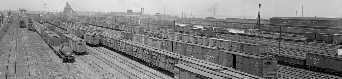

The B&O Wheeling, WV freight house and docks as seen from across Wheeling Creek. This is one of the HABS/HAER images taken before the facility was leveled.
As outlined in the previous post, I am contemplating a new HO scale model railroad in a spare bedroom of 9′ 10″ by 16′. I want to keep this layout simple to ease building, operating, and eventually tearing down and moving. I’m also lucky to have prototype details in hand to assist with two different projects. A portion of the Wheeling & Lake Erie was detailed in the last blog post, so now it is time to share details and thought processes for a second prototype.
The Baltimore & Ohio Railroad operated a pocket-sized freight terminal shoe-horned into an odd plot of land next to the downtown business district and just railroad east of the Wheeling, W. Va. passenger terminal. As far as I can determine, this freight terminal was a part of the original infrastructure of the railroad when it began laying rails in Wheeling about 1850. Here’s an idea of some of the track the B&O operated along the banks of the Ohio River. This is an edit of a B&O a valuation map from 1920. Most of the images here can be seen in a larger size by clicking on the image.

It’s a linear operation. I assume freight cars were set off on some of the yard tracks to the right of the creek that would be spotted at the freight terminal and team track yard on the left side of the creek. It seems there is another team track yard just above the yard tracks and to the right of the creek, but I don’t think that will fit into the layout space so it will be ignored at this time. The valuation map offers this more detailed drawing of the freight house and team track yard area in a larger scale on an empty part of the map.

The valuation map gives me the basics to move forward in designing a layout based upon a small slice of the prototype. As the map has lots of detail, I created a simple schematic to cut through the noise and gain a better understanding where the tracks were. This only takes a few minutes to create and can show operating segments that can be pulled away to fit easier into an available space.

With the schematic in hand, I work on a very rough sketch to see how basic track elements can be placed into the layout space. I thought an angled design would be a better fit for a smaller room.

But when I attempted to create a scale drawing to follow the sketch, the team track yard would not fit. This was a bit frustrating as I didn’t think there was much track here to be complicated. I took a few days off from drawing and set up my hobby bench, then two light bulbs went off in my head. I had forgotten that the hobby bench was integrated into the support of the benchwork on the last layout, so I ended up with additional benchwork that I had not anticipated.

After this realization, I went back to reviewing the schematic and I noticed this terminal has three distinct operating sections. There was the yard where freight cars came in from the mainline and there is the freight house area. Note the team track yard access track has a separate track coming out of the yard and crossing the creek. I decided to separate the freight house and team track areas more on the layout design than in the prototype to offer two different operating areas and ease the fit into the available space. After a few minutes with pen and paper, I came up with this rough sketch of another possibility.

This latest sketch inspired me to create a rough scale drawing. I spent a few hours over a couple of days, first drawing the staging yard area then fitting in the freight house and team track yards. Due to the room size, I was unable to draw everything on one sheet of graph paper so this image is a composite of the two drawings.

The drawing scale is 3/4″ equal to one foot, and each block on the graph paper is four inches square. Not all of the benchwork boundaries are drawn. I’m used to making real size adjustments as track is installed so I don’t bother adding corner boundaries on a rough drawing. The track height will be 52 inches. Number 6 track switches are used in all but the team track yard, where number 5 track switches fit better. This is all a slow speed switching district with shorter freight cars of the 1926 era, so the sharper angled track switches should work fine. There are no grades and curves are a mix of 24 and 26 inch radii. The switchback tail of the team track yard follows the length of the prototype. There is hardly clearance for one loco and four 40 foot freight cars. The prototype team track yard had a 24 car capacity so this fits well in a small model railroad application.
A bonus for this freight terminal is easy access to prototype documentation. The Historic American Building Survey and Historic American Engineering Record (HABS/HAER) measured and photographed the freight house just before it was razed in the mid-1970s. Here’s another view of the original building. The wall of buildings in the background also catches my interest.

Now it is time to choose between two prototypes and two layout designs. There are pros and cons to both of the possibilities, and each follows my “keep it simple” mantra. I won’t be dithering on this decision as I am also following another mantra; “keep moving forward”. I’ve begun cutting lumber for benchwork and should have some sections standing in the hobby room soon. An upcoming blog post should reveal progress on my next model railroad.
Your comments are encouraged. All comments are reviewed and approved before they appear here.
Hi Eric!
While the B&O is cool and all that, I’d stick with your core interests of the Wheeling in the 1920s. Overall, even if you do go with minimalist scenery and even foam core buildings, keeping to what you know best will target your modeling efforts better, especially when it comes to things like W&LE versus B&O cabooses, engines, and even house cars and lineside sheds. We all only have a finite amount of modeling time on this Earth, and there’s no point in spreading it too think on things that aren’t of principle interest to you. That’s why you don’t find me doing goofy things like modeling 1/700 Japanese destroyers or 1/24th scale KV-1’s! (well, I DO have a stash of 1/24th scale armor and troop kits stashed…….)
Eric,
You might find 1926 B&O engine and caboose equipment easier to find than W&LE.
From your earlier clinics, I believe the W&LE offered interchange possiblilties that are absent from the B&O version above.
Travers, Stavac, modeling B&O’s Baltimore Terminal in 1952
Thanks for stopping by and commenting, Ray!
I do agree with everything in your comments but there are other parameters to this project that go beyond the prototype. I do have a couple locos on hand to use for the B&O freight terminal layout. I don’t think B&O cabooses would be needed for those operations. The freight car fleet would be similar but shift away from hoppers and focus more on box, ventilated and refrigerator cars with some flats and gondolas for the team track yard. I have models to use on either layout design on hand. My decision comes down to room use parameters and time. Keeping this project simple is a major consideration. We will be in this house at least a year, possibly two years, and I’d like to be up and running within a couple of months.
Since the spring of 2009, I’ve moved three times and understand finite amounts of modeling time all too well. Freight car models have been one element that has transcended each layout project. I want to build a layout so I can use the models I’ve built. Either of these designs will work well for the freight cars I have on hand, whether they are ready to roll or still need to be built.
My build decision won’t be about either prototype, it will boil down to other considerations.
– Eric
Greetings Travers! Thank you for your comments.
I must admit to an affliction common to many model railroaders. I have purchased many items over the years because it looked cool, or I thought I could use it at some point down the line, or it was just too good a price to pass up. One of these items happens to be a Sunset brass B&O E-24 class 2-8-0, which was a fairly common locomotive used on the B&O lines around Wheeling in the mid-1920s. An old MDC 0-6-0 kit is also on hand, which may be converted to a B&O D-7 class loco with a little effort. Similarly, a couple of Spectrum 2-8-0 locos I have can be converted to W&LE locos used on their Cleveland Division in the 1920s. The Wheeling bought several LS&MS consolidations with large drivers in the early 1920s. The Spectrum drivers are close enough, and with a new tender and cylinders these Spectrum locos would be the main local power. The W&LE also built several 0-8-0s using the USRA plans, and I happen to have a couple of the Proto2000 0-8-0 models. So, locomotive models are already on hand.
Cabooses are also not a major concern. As I noted in the previous response to Ray, I don’t think the B&O used cabooses in switching the Wheeling freight terminal. For the Newburgh layout, a couple of friends have shared kitbashing steps to transform MDC wood sheathed cabooses into pretty close W&LE models. The freight car fleet would be similar on both layouts, but more box, ventilated and refrigerator cars would appear on the Wheeling freight terminal. All of these models are on hand ready to use or ready to build.
You are correct in noting more interchange. opportunities on the Newburgh design as there is a PRR connection, and the Newburgh & South Shore exchanged trains directly in the East 93rd Street yard. The yards on either design are basically active staging yards where freight cars are removed or added during or between operating sessions to offer diversity and interest.
I don’t expect this next layout to be a lifetime project, just something to build, enjoy and learn from as my hobby journey continues. I miss the regular operating sessions I attended in New York and New Jersey, so getting something rolling quickly here will help to fill that void. If I’m lucky, my layout work may inspire local modelers in their efforts and we could have regular operating sessions on a few layouts in El Paso and Las Cruces.
– Eric
Eric,
This is a great idea for a layout in the space you have available. It is a wonderful opportunity to model a prototype track layout almost to exact scale while doing some fantastic urban scenery. For that reason, I feel you should rethink your trackplan.
Start with the track west of Wheeling Creek; try to model this as close to the prototype as possible. Why do you provide only 2-foot-deep benchwork for this most important feature, a ready-made “layout design element?” Make it 3′ deep and I think you can fit all the track. You have the length you need if I understand the distances on the drawing correctly; the whole scheme west of the creek is only about 7′ in length. If you cannot widen the benchwork here, then flip the whole thing around, and build it as though you were looking south. Gives you more length for creek and everything, and you might have room for yard tracks (team tracks?) east of the creek.
In any case, the creek with bridges should be there. If that means building a new section, do it. You’re letting the tail wag the dog (or, the caboose pull the train) if you start with benchwork and make the track fit, especially if you get away from our tendency to look north with east to the right.
Why not have two staging yards representing points east and west? Does the mainline towards Pittsburgh start a grade separation west of where your complex vears off? A slight grade separation would isolate the staging some. I’d put staging in one direction along the far wall, and staging along whichever leg of the benchwork does not have the complex track.
Hard to explain in words, but I think you could do a lot here. Whatever you do, preserve that great scene! Maybe staging along the two side walls and your scene along the far wall. –Mike
Eric,
The layouts you’ve offered both have interesting prototypes and operations.
The Wheeling (B&O) freight house/team track would be simpler to get built and operating. The number of sidings, by my count, come up to 11 on the freight house design. The cars for the freight house would be sorted in the yard and simply spotted as a “cut” of cars, correct? The team track adds a little more action since there is the switchback that limits train length. Would team tracks be organized similar to the freight house track for operation? I don’t know if a team track would be “pulled” so that a couple of cars that are ready to move are made available for the next freight.
The 93rd Street (W&LE) design is more involved in it’s scope and design. Again, I counted the sidings shown and came up with 19, including the N&SS interchange and the PRR interchange tracks. There are more individual sidings receiving and shipping different products and therefore a more diverse freight car fleet (in my humble opinion) would be needed.
In my (not so) humble opinion, I think the 93rd St. design would be a more satisfying operation than the Wheeling freight house plan. Both would bring new friends into the world of prototype layout design and operations.
Can’t wait to see where you go from here!