
Dave Parker returns with an upgrade on an Accurail HO scale USRA hopper.
Over the past few years, I have accumulated several Accurail USRA twin hopper kits in both the 24xx (as built) and 25xx (modernized) series. At least two of them will require complete re-lettering in order to follow the prototype but one is, atypically, exactly correct for my 1934-35 layout. It is a Delaware, Lackawanna and & Western car (#2503.2) with correct lettering, and a reweigh date of April, 1933 – perfect! Absent any need to repaint, I initially decided to more-or-less “shake the box” with this kit, and not upgrade the cast-on grab irons (as has been documented elsewhere).
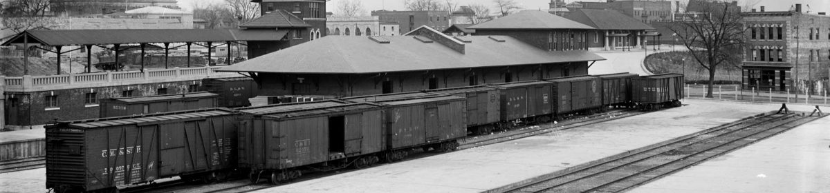
In 1919, the DL&W received 800 USRA 50-ton twin hoppers, numbered, 81000-81799. Thanks to Ray Breyer, I was able to obtain a number of excellent photographs from the early 1920s taken from multiple viewpoints, plus some photos of virtually identical cars still lettered for the GET (Government Equipment Trust). These hoppers had the Blackall brake levers and Carmer uncouplers that were almost universally applied to the USRA cars as built, as seen in this image.

In comparing the kit with the prototype photos, I decided there were four candidate areas where upgrades or added details might be justified (and perhaps doable):
- Correct split (KD) brakes.
- Interior gussets and cross-bracing
- A train-line and air hoses
- Carmer uncoupling levers
Arguably, all of these details would be “excessive” if I wasn’t going to upgrade the grabs, but I wanted the experience to help me do a better job with future builds. Included in that list is a Tichy Train Group 4027 kit which served as a valuable point of reference (and departure) for this project.
My approach to the KD brake hardware (using Tichy’s 3034 set) was similar to that in Eric’s 2012 post, but with a few differences. First, in looking at the prototype photo above, I noticed that the cylinder sits rather high – about 5 inches above the top of the end sill. In contrast to the Tichy kit, which mounts the cylinder quite low, the Accurail’s pedestal looked to be about the right height. All I did was grind off the tab that fits into the supplied AB cylinder, file out the “slot” on top, and attach the KD cylinder (pre-drilled for the pipe connection to the reservoir). I also filled in two extra mounting holes with red putty (Bondo), and ground off a couple of tabs on the right-hand diagonal brace. To place the KD reservoir at approximately the correct height, I simply glued one of the Tichy-supplied saddles to the same diagonal, but a bit further back from the end-sill. Here’s a comparison between the original underframe on the left and the modified work on the right.

In other types of cars (e.g. gondolas), the KD reservoir is attached to the underside, with the dirt collector pointing downward. The same orientation is required here (collector downward), but the mounting bracket that is cast onto the top of the reservoir needs to be shaved off and sanded smooth (see photo 4). I also cut off the dirt collector, saved it for later reinstallation at a 90-degree angle to the axis of the reservoir, drilled a #78 hole into the triple valve to accept the train-line connection, and a #80 hole to accept the retainer line. Here’s a before and after view of the reservoir work.

I then mounted the reservoir on its saddle, and added a strip of green card-stock to represent the retaining strap that runs over its top, as seen in the next image. I bent a piece of 0.018-inch wire to represent the 1-1/4-inch NPS pipe that runs to the train line. I cut off the top of the saved dirt collector, filed V-notch into it, and glued it to the wire with CA. A small blob of gray epoxy was placed on top to recreate the overall shape of the dirt collector, and this assembly was glued to the reservoir and to the diagonal brace. Note in the earlier prototype image the installation had a quarter-turn cutoff valve just to the right of the dirt collector, but I did not try to add this detail.

To better match the prototype, I tried putting multiple bends (elbows) in the line connecting the cylinder and reservoir. Assuming this was 1-inch NPS pipe (1.3-inch OD) in the prototype, I first tried 0.015-inch brass wire, but the result looked clunky and the bends were not sharp enough. This was redone using 0.0125-inch wire (1.1-inch scale; not exactly correct), and the result was better. This pipe was glued into the holed in front of the cylinder, but simply tacked flat to the back of the reservoir which cannot be seen. In attempt to simulate the elbow fittings, every bend in both pipe connections was given a small drop of gel-type CA adhesive.
Final details included a Tichy-provided brake lever, with the brake cylinder clevis twisted to provide the correct angle. As per the prototype, I wanted the vertical mounting strap that runs from the sill to the cylinder-to-reservoir connection, but I fabricated this from 0.004-inch Mylar rather than card-stock. Last, I pre-installed a piece of black 0.008-inch wire (soft brass, cadged from my fly-tying supplies) to represent the retainer line, leaving it cut long until the underbody was mated to the car body. All of the brake details were sprayed with Polly Scale Steam Power Black prior to assembly.

The interior gussets and cross-braces were tackled next. The Accurail kit has gussets molded into the body. Based on my Tichy kit, these are not quite the correct size and shape for the original USRA design, or for the NYC’s modified cars. Modifying them seemed daunting, so I left them as is. Eric fabricated his cross-braces using 4-inch scale square stock installed in a “diamond” configuration, but I decided to go a bit further. As per both the Tichy and MTH cars, these braces are look like a “+” sign in cross-section, but the horizontal arms are triangular in cross section. I thought about some simple way to simulate this, and came up with two pieces of 3/64-inch styrene angle (Plastruct 90501) glued back-to-back to form a “T”. The fourth “arm” was faked by applying 0.040-inch half-round (Plastruct 90880) to the flat side of the T. I glued up about 4 inches of this “stock” shape, and then carefully cut and sanded three lengths to achieve a friction fit. I mostly eyeballed these to line up with the three corresponding ribs, but also made a simple cardstock jig to help set the exact height, and then secured them with a dab of styrene cement. They look pretty convincing from a distance and in the image above, but I did not try to replicate the rivet detail found in both the Tichy and MTH versions of these braces.
Before joining the body and underframe, I added one additional detail: the brake release rods. Small #80 holes were drilled in the triangular gussets on each side, and an overly long piece of 0.0065-inch black wire (also from the fly-tying box) was threaded through. I simply left this loose until after assembly, tightened it over the top of the reservoir, tacked it down there with a drop of canopy glue, and then bent over and snipped off the ends.

For the train line, I first tackled the air hoses. This was my first chance to try the molded rubber hoses from Hi-Tech Details (#60380) and I am impressed: the detail is quite good and they cannot be broken off the way styrene hoses fail. The prototype’s mounting bracket is a bit more elaborate than I could manage but for that matter so is draft gear housing, as you can see in the above image. I settled on simplified approach by mounting a suitably sized ring-eye in a #73 hole drilled into the side of the draft gear box, affixed with CA. The ring-eye was fashioned from a fishing hook also scrounged from my fly-tying kit. The rubber air hose was pre-threaded through the eye, later fixed in position with CA, and trimmed as needed. Here’s a look at that detail.

I wanted to create the three straps that suspend the train-line along the bottom of the right-hand side of the car. This was one of my early forays into the wonderful world of Mylar. From a prototype photo, I sized these straps as ca. 12 x 3 inches. Using Powerpoint, I created an HO scale image of these including the four needed “rivets” (or perhaps carriage-bold heads). I printed up a large number of these (and other color-coded detail parts for future use) using an inkjet printer and matte-finish Mylar from Grafix that is 0.004-inch thick. Here’s a look at the printed sheet.

Before trimming the parts to size, the rivet heads were added using the old dull-pin trick. The trimmed straps were first tacked to the side of the car using canopy glue, and then affixed with CA. The train line was fashioned from 0.020-inch phosphor bronze wire, and had been pre-bent using a simple hand-drawn template that I had created. It was first affixed to the A-end bolster, the B-end air hose, and the pipe from the reservoir that protruded just below the side-sill; I used small dabs of epoxy for durability. After full cure, the three straps were then tacked to the train line with CA.

As far as I know, the routing of the train line is correct. The way it turns the corner at the B end, and then joins the angle cock with an elbow fitting can be clearly seen in several prototype photos. The A-end routing is murkier; the pipe is clamped to the bolster, and then travels upward, where at some point it goes up and over the center-sill and draft gear housing, before running straight into the back of the angle cock. Absent any clear photos, I simply terminated the line just “downstream” of the bolster, and did not detail the largely invisible connection to the A-end air hose. At this point, I touched up all of the bare parts with another spray coat of Steam Power Black.
I wanted to include the fourth hanger strap for the train-line on the B end, but could due to lack of clearance. On the prototype, the train-line is slightly outboard of the end-sill, but not on the model; the draft-gear box does not protrude quite far enough from the end-sill to allow for the correct arrangement of these components.
I was also going to a stab at a long-standing project: home-made Carmer levers fabricated from Mylar. But in comparing the ends of the prototype and the model in the image below, I realized that this would prove challenging. On the Accurail ends, the grab on the left side of the end-sill is too low, too close to the draft gear, and is a drop grab, not straight as on the prototype. There really isn’t enough room to properly mount the boss for the Carmer assembly. Thus, I decided to shelve this attempt until I build a USRA car with “super-detailing” (i.e., scale grabs) that will allow me to better position these components on the car ends.

For the Andrews trucks, I decided to use a set of Accurails from another kit (the 25xx series comes with their “Bettendorfs”). Although these Andrews trucks are a couple of inches too long in the wheelbase, and not an exact match for the USRA Andrews design, they are appropriate for a model with this level of overall detail. Kadee #533 code 88 rib-back wheelsets replaced the original wheelsets. The couplers are the Kadee semi-scale “whiskers” model (#158) with the trip pins snipped off.

The completed hopper is now ready for a trip to the weathering shop. Yet another great learning experience for me as I think the techniques I developed here will serve me well when I undertake a more contest-quality version of the USRA twin hopper.
Thanks to Dave Parker for sharing another freight car modeling experience. Feel free to share a comment in the section below. Please follow the instructions so your comment can be posted. All comments are reviewed and approved before they appear. To subscribe to this blog, enter your info for a comment and check the last box to notify of new posts by email.
Very nice job on the upgrades. I like your idea using the mylar for the strap hangers.
George Toman
Enjoyed reading this, very interesting technique for the trainline