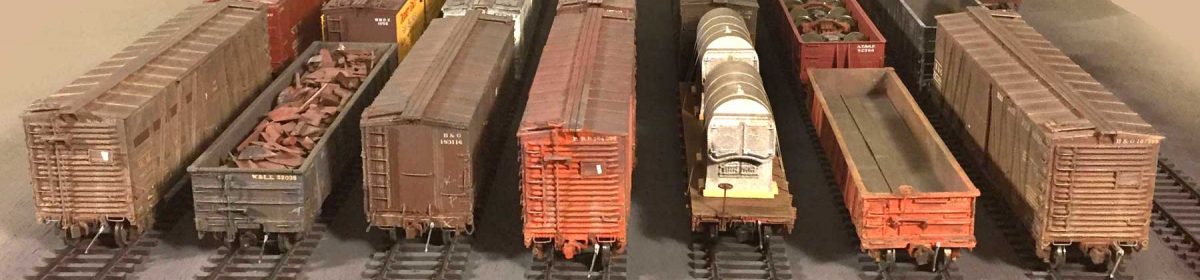
It has been awhile since I tackled a resin freight car kit, so I dove into a Westerfield box and got something rolling. I’ve long wanted to build one of the Canadian Pacific 36-foot, single-sheathed Fowler design box car kits. There were plenty of prototypes rolling around in 1926. The kit built quickly with only a couple of head scratching spots. I liked it so much that I also built a kit for a similar 40-foot Fowler design clone! Follow along on the latest resin freight car kit build.
Here are the two kits for this summary.
Westerfield 1501 – 5-foot door, 36-foot Fowler box car, Phase 3A/B Canadian Pacific
Westerfield 6403 – 40-foot Fowler Clone box car, Denver & Rio Grande
The Canadian Pacific car kit was built first and completed with work stretched across five days.

The first Canadian Pacific cars were built in 1909. These cars were among the earliest to use straight steel centersills and an external steel truss in the car design. The Westerfield data sheet notes about 75,000 36-foot box cars were built to this basic design between 1909 and 1923. The Canadian Pacific installed more than 33,000 of these box cars between 1909 and 1914. The Canadian National had several thousand in service, too.

On day one, I unwrapped all the parts and reviewed the instructions. Yes, please take time to review the kit instructions. There are different details to install depending upon what version you are building. I often pencil notes in the margin. Sort through the parts and identify them based upon the info in the directions. After a pass or two through the directions, the major parts are cleaned of flash and washed with warm water, Dawn dish detergent, and an old soft toothbrush. The above image was taken before the flash was removed from a few parts.

Once the parts are dry, holes are drilled for grab iron installation in the sides and ends. The retainer, retainer air line, and brake step platform are installed on the B end casting. Eyebolts are added for the uncoupling rod. The doors were also installed at this time.
Cyano-acrylate adhesive (CA) is used to fasten the wire grab irons and other details in place. I put a drop or two on a small square of a plastic parts envelope and use a length 0.015-inch wire to apply small amounts of the CA to the parts. After the adhesive dries, the excess wire is snipped from the backside of the castings and the areas are filed smooth with a flat file.

I could not have detailed this model without a handful of images that Rick DeCandido shared. Rick has a blog documenting his layout adventures and he knew I was contemplating a Fowler kit awhile back. He came across a Fowler box car on display in Toronto and took several photos. These were very helpful as I have few prototype Fowler images in my own archive. The above image was a huge assist as the brake step details were installed.

Another of Rick’s images helped me understand the details on the left side of the end sill where the brake staff ends. I can’t thank Rick enough for his generosity. His images really helped move this project along.

Day two is filled with several tasks. First, holes are drilled in the bolsters for the truck mounting screws. These holes are tapped for 2-56 machine screws. The car weight is positioned on the floor of the underframe casting. A pencil marks the end points. Barge contact cement is applied to the floor and one side of the weight. These are set aside for fifteen minutes before carefully joining the weight to the car floor. The pencil marks help show where the cement needs to be applied and where the car weight fits.
The sides and ends are assembled next. Short lengths of square styrene are glued flush with the ends of the sides to allow more surface are in attaching the ends. These styrene parts need to fit in the space between the car floor and the roof truss. Mark these locations with a pencil on the inside of the side and end castings. Once the styrene stock is set, Barge contact cement is carefully applied to the parts that will be joined. Allow ten minutes for the cement to become tacky before proceeding.
I like to join opposite corners first to ensure they are square and fit properly. A small machinist square is handy to check the fit at this point. Once the two sets are together, join up the other corners in a similar manner. After the ends and sides set up, the underframe casting is installed. I needed to add 0.015-inch styrene strip along each side of the underframe to widen it for a good fit between the sides.
After the underframe is installed, all the side and end joints were reinforced with CA.

Underframe details were installed next. This is where you need to take time and understand what parts are needed and where they go. The floor crossties are easy to spot as there are many of them and they look like C-channel stock. Here’s a look at other parts with call outs.

I had difficulty with the bolster pieces and missed installing the Top Bolster Cover Plate. I think it will be fine in the end. This is step 20 in the instructions.

I think I also erred when installing the Y-shaped bolster center castings. I installed the narrow end over top of the square portion that extends from the underframe casting. The instructions seem to indicate the Y-shaped bolster center castings should be trimmed to fit between the bolster and that square portion extending from the underframe. I didn’t realize this until after the bolster cover plate was installed. The couplers were installed and checked for the proper level. All was fine, so I won’t be worrying about it.

The work on day three wrapped up the underframe details. The K brake system parts, brake rods, and hangers all installed smoothly. The straight centersill makes the brake system an easy install.

The corner grabs were added on the roof casting. Excess wire was snipped from the back of the casting and filed smooth. Instructions were followed to prep the casting for installation.
The model was weighed and came up a little light. Two half-ounce tire weights were fastened to the car floor with Barge contact cement to finish the day.

A couple of bulkheads were installed on day four to keep the sides from bowing. These were made from 0.040-inch sheet styrene and can be seen in the image above. These need to be the same dimension as the interior width at the ends and match the width of the floor.

The sub roof casting was installed and once that was set, the thin roof casting was glued into place. I was surprised after the roof casting was in place because it was a tad short. Thin strips of styrene were added at the ends.

The running board and end supports were installed next in the build process.

The final details were installed on day five. A-Line wire sill steps were substituted for the kit supplied parts. For these Canadian cars, a step needs to be installed under the end ladders, too.
The uncoupling levers were installed at this point, too. These were bent from wire and threaded through the eyebolts on the end sills.

The vertical brake staff and brake wheel are the final details installed. I use a heavier wire for the brake staff so it survives operating session handling. It is 0.020-inch in diameter and looks different from the wire used on the grabs and the smaller diameter wire used on the retainer line.

And here’s the finished kit build, ready for the paint shop. An air hose will be added after the model is painted. I think I logged about 12 hours of work on this model across five days.
40-foot Fowler Clone box car, Denver & Rio Grande Western
Inspired by the 36-foot Fowler box car build, I dug up a 40-foot Fowler clone box car kit. The Wheeling Freight Terminal has few freight cars representing western railroads, so this D&RGW car will help improve the western representation.

As per the Westerfield prototype data sheet, The D&RG received 1500 of these cars in 1916. These Pullman built cars were among the earliest 40-foot single-sheathed box cars built. The Chicago & Northwestern, and Rock Island railroads received similar cars in the mid-Teens.
I didn’t take many in-process photos during this kit build. Much of the construction followed the same steps as the previous Fowler box car kit.

The main parts were cleaned of flash and washed. Holes were drilled and grab irons were installed. The model build proceeded quickly on the first day. Note the corner reinforcement pieces and the bulkheads near the car center. I needed to add 0.015-inch styrene strip along each sides of the underframe to widen it for a good fit between the sides.
I found the line up of end and side castings needs to be carefully positioned. There is a slight offset and part of the end castings extend beyond the sides. You can click on the above image for a larger view and see the offset on the right front corner.

The bolster assembly was much easier on this model than the previous. There was only the bolster piece and the cover plate to install.

Here’s a look at the smaller parts with labels.

This model did not have a sub roof casting. It had a few trusses and a ridgepole to install. This work is a bit tedious but proceeds easily. A key is keeping the ridgepole straight. Material will need to be removed from the ends of the trusses so they fit snug.

The underframe details fell right into place. The cross members are a bit tedious to install because many needed to be trimmed slightly for a proper fit. This is not difficult work.

The roof casting and running board details were installed. I waited until the last few steps of the build to install the delicate ladders. Use care in sanding the flash from these castings. Take your time and use a light touch when scraping away any remaining flash.

The vertical brake staff, staff support, and brake wheel were installed after the sill steps. It was at this point that I noticed the roof casting did not fit onto the end casting properly. I worked to ensure the roof truss parts that were attached to the back of the end castings had the same plane across the end angle, but I guess I didn’t quite get it.
In full disclosure, none of my resin freight car kits are perfectly built. There is some odd mismatch or something with each one of them. While this visible mistake where the end and roof castings meet is disappointing, I find its par for my kit builds. I seem to make a new error with each build. And so it goes.

It’s a special thrill when I can put a new freight car on the tracks and couple it to another. Even though it’s not painted, decaled, or weathered, I have a great sense of accomplishment when the wheels hit the rails.

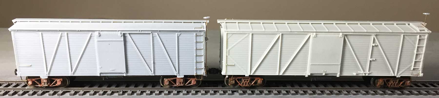
Here are both Fowler box cars side by side. Note the D&RGW car does not have a brake step. The brake staff is taller because there is no brake step. Apparently, the prototype cars never had that feature and some were in service into the early 1960s.
While these two models follow prototypes built to similar designs, there are differences in hardware. The roofs differ as to the ladders. There are door stops on the D&RGW car but not the CP car. They each rode on different trucks, too.
It was great fun building these two box car kits. I’ve got another resin freight car kit on the workbench now that is different from anything else I’ve built. I hope to share that soon.
Thanks for dropping by and reading my blog. Feel free to share a comment in the section below. Please follow the instructions so your comment can be posted. All comments are reviewed and approved before they appear. To subscribe to this blog, enter your info for a comment and check the last box to notify of new posts by email.
Next time you’re in a dollar store, look for a cheap battery operated toothbrush. They work great for reaching the nooks and crannies of the car when cleaning the castings.
That’s a great tip. I’ll keep my eyes open for one of those. Thanks Dave! – Eric
Superior work.I have built several.Wish I had waited for these tips.I believe the Fowlers are called Dominions in Canada.There are subtle differences
Thanks for your note, Armand. I’m aware of the Fowler/Dominion name issues but the kits are marked as Fowlers, so I stuck with the kit name to avoid confusion. – Eric
Eric,
Nice description of the build process. I generally follow that pathway, too. I did not notice the errors you mentioned, but these are always more evident to the builder. I don’t think I ever made a perfect build on any of my resin kits and I’ve built many, many of them.
I do like the kits you’ve shown, here, and hope we get to see them after painting and weathering. Very nice builds.
Keep up the good work!
Jim
Thanks, Jim! I have decent painting weather ahead plus several models ready for the paint booth. Maybe I’ll have these completed to display at RPM-East in March! I’ll cross my fingers. – Eric
Eric, another great build in line with many others. I always enjoy following your builds and the Wheeling Freight Terminal. Merry Christmas if I don’t put up another post before then.
I have to say following your work is sorely tempting me to change eras, however I have been able to resist so far. The twenties and thirties are a very appealing time period and even more appealing than the late sixties my other era that tempts me to change from 1959. I will resist, to change at this point would be madness on my part.
I am looking forward to seeing the paint and decals on these fine models you have built.
Thanks for your comments and following along, Rob. I’m glad the features here are making people think differently about modeling the 1920s. I understand if you don’t want to make hat drastic of a change, but if you look at the post-WW2 years of 1946-1953 you will see a greater variety of older freight carsin the last years of service. Plus, there’s more great steam running then!
I hope you have a great holiday season! – Eric
Hi Eric,
Great post; very enjoyable reading. Those box cars look absolutely fantastic!
I think you have done a very fine job of it….they don’t call them craftsman kits for nothing. I look forward to seeing them painted, with decals, your fine weathering and maybe in a train on your layout.
Take Care
Rick
Thanks, Rick! Your photos really helped me finish the Canadian Pacific car. I hope it will be painted and decaled by this spring. – Eric
How can I watch the previous blogs ??
Kevin, click on the header and it will lead you to the main page. Or, just click here. – Eric
Once again, your insight and pictures are helping me finish my two kits I started. Much like my automobile projects, I am finding a couple ‘extra’ parts that I am sure should go somewhere. 🙂
Eric,
Great series of articles, very much enjoy reading them. What type couplers do you recommend for these kits? Thanks
Jim, I prefer a scale-size coupler for my 1926 era freight cars. My standard is the Accurail Proto:HO coupler but I have installed Kadee #58 couplers on several cars. I recommend you set a standard by checking the various couplers. Note that I do not use the glad hands on my couplers. The Accurail proto couplers are a kit and the glad hand is optional but the Kadees need a snip to remove the glad hand. Many people like the Sergent Engineering couplers, too. These are working, scale couplers but not compatible with other manufacturers. It’s a personal choice and best to set a standard as you move into building resin kits. – Eric
Westerfield’s “Fowler” car kits have a pad on the truck body bolster about 40 thou thick. It appears that the floor pattern was made per prototype drawings, then this pad added to the master to mate with a HO truck of NMRA bolster height.
This is not an issue if using trucks of NMRA bolster height such as Tahoe’s AC&F archbat truck (which is very close to the original truck on the Canadian cars) but to use Proto’s “Simplex” truck modelling the trucks fitted to these cars by Canadian roads later, you have to shave that 40 thou pad off. A razor saw blade level with the bottom of the centre sill will cut it off neatly, followed by careful sanding to reduce the bolster height to use the Proto truck.
Steve Lucas
Thanks for the notes, Steve. I wish those Proto trucks were available. The Simplex elements made for a slightly different appearance. – Eric
I got lucky, being able to purchase a few of the Proto Simplex trucks for use on future builds. Modelling a grain-hauling line in Eastern Ontario circa October, 1956, I need a few “Fowlers”. I’ve built about eight so far from Westerfield kits , with a few more under construction using modified Kaslo Shops kits. A couple of my “Fowlers” have received these trucks.