I’ve seen and heard lots of good comments on the new Accurail HO scale, 36-foot, double sheathed, box car kits. But many people seem puzzled on building the underframe. As an Accurail kit, we have come to expect parts to fall together easily. This kit is no exception; there are just a few more parts to carefully set into place. Follow along on a tutorial to help you assemble the underframe on these fine kits.

Here are the underframe parts. The sprue on the left has the brake levers and rods cast in a flexible material. Above the main underframe part is the sprue with the center sills, K brake component, cross bearers, coupler box covers, and the brake wheel.

Basic tools help with a clean assembly. Styrene cement is used in a few spot applications. A sharp blade is a must in removing larger parts from the sprue. The orange handled flush side cutters are used to remove the parts from the sprue, but cut near the sprue and clean off the nub with a sharp blade.

These parts have been roughly trimmed from the sprue. The toothpick is pointing at the excess material a sharp blade will remove.

My favorite cutting tool is a single edge razor blade. I start each project with a new blade for clean cuts.

The brake levers and rods are a one piece casting with tight sprue clearances. I use the razor blade to cut the gates near the sprue.

Then the blade is used to remove those leftover nubs. Take your time to do a nice job here. We still have more parts to prep before assembling.

The K brake casting is nicely done.

The clevis fits over the long brake lever. There is a small, half-round dimple on the brake lever where the clevis fits. You can see it in the above image as the light reflects off of the area.

Check the fit of the brake lever so it slides right into place with the clevis. Do not glue these at this time. Just check the fit.

At this point, we can install the brake cylinder to the proper center sill part. It only fits one way.

A touch of styrene cement holds the cylinder in place. This can also be applied to the back side of the center sill casting.

Now we come to the part that is not typical of a model railroad freight car kit. The brake rod is threaded through the other center sill first. The rod attached to the long brake lever needs to go through the wide slot.

The small forked end of the shorter brake lever is inserted into the small hole on the back of the center sill casting.

A touch of styrene cement on that interface keeps the part in place.

Like I said before, the brake rod casting is made from a flexible material, but don’t bend it too far.

Now that other brake rod end is threaded through the center sill with the brake cylinder installed. The long brake lever goes through the other wide slot to interface with the clevis on the brake cylinder.

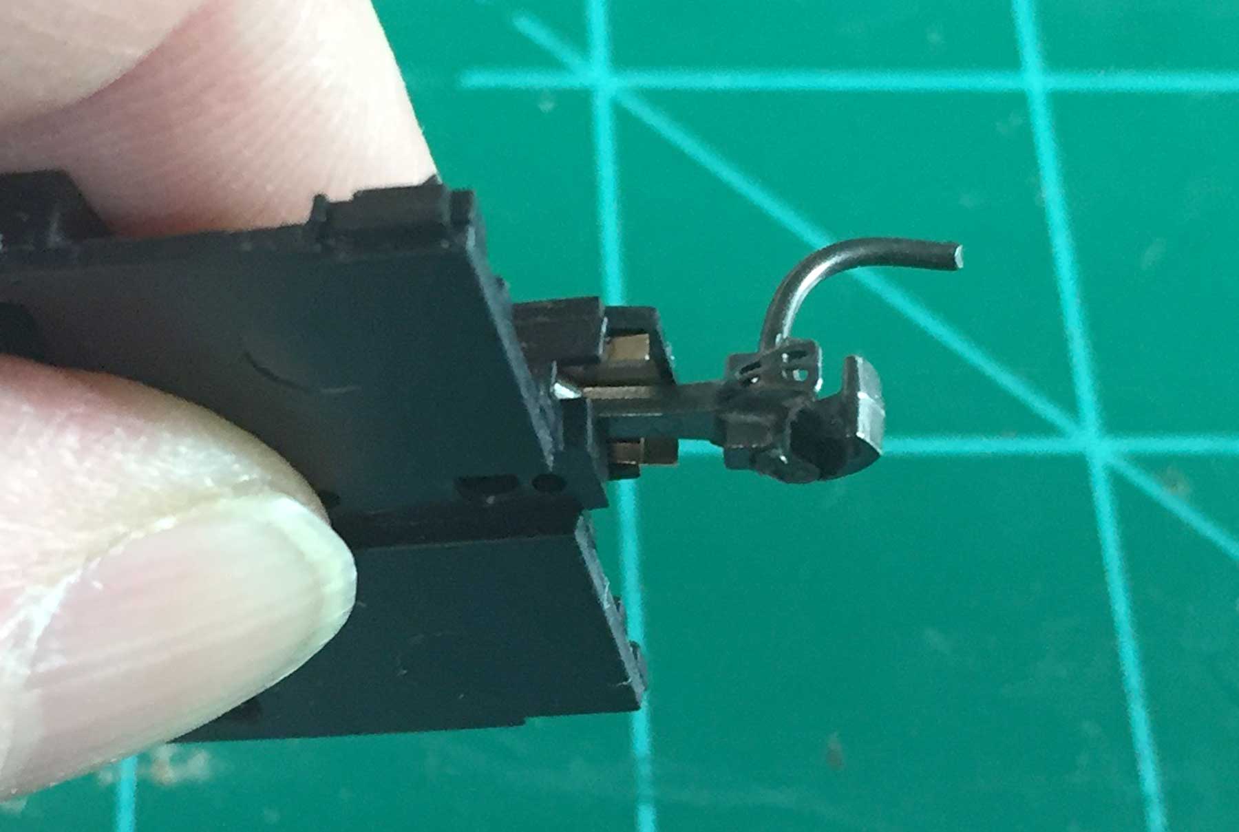
Here’s how the assembly looks at this point. My fingers are holding it together in this image.

Some masking tape applied to the bottom of the center sill parts holds the parts in place for the next step. Blue painters tape was used here. Sorry I forgot to include this with the tools at the beginning.

Bring the five cross bearer parts close to the assembly. Don’t worry about the tape holding the centersills at an odd spacing.

Carefully install the two cross bearer castings at the ends of the centersill. Adjust the centersill spacing on the tape so the cross bearer fit right into place. The angled part of the cross bearer castings is facing down toward the tape for this installation. The top is flat as it supports the car floor.

A touch of styrene cement fixes the two cross bearers in place.

Let the cement dry for a moment then install the remaining cross bearers. Touch them with the cement to finish this part of the assembly.

When the cement is dry, this is how your assembly should look.

Now we can check the installation on the underframe casting. The center sill casting tabs are keyed to slots on the underframe casting.

Snap the assembly into place. It will only fit one way.

Touch the tabs with some cement from the top side of the underframe casting. Allow this to completely dry before installing the car weight.
Coupler Installation
I’ve also heard of modelers having difficulty installing Kadee couplers on these models. They say the flat coupler spring does not fit. I noticed this several years ago with other models and started to trim parts of the flat coupler spring.

Here’s a comparison of a trimmed spring on the left and a spring straight from a new package of Kadee #58 couplers. Note the excess material at the front of the spring.

The part at the back of the spring is also a bit tall. These need to be trimmed with side cutting pliers and the rough remains carefully filed away. Once the spring is modified, it fits fine.

Install the spring in the lid first, then add the coupler.

The assembly slides into place. Install the kit provided screw to finish it up.

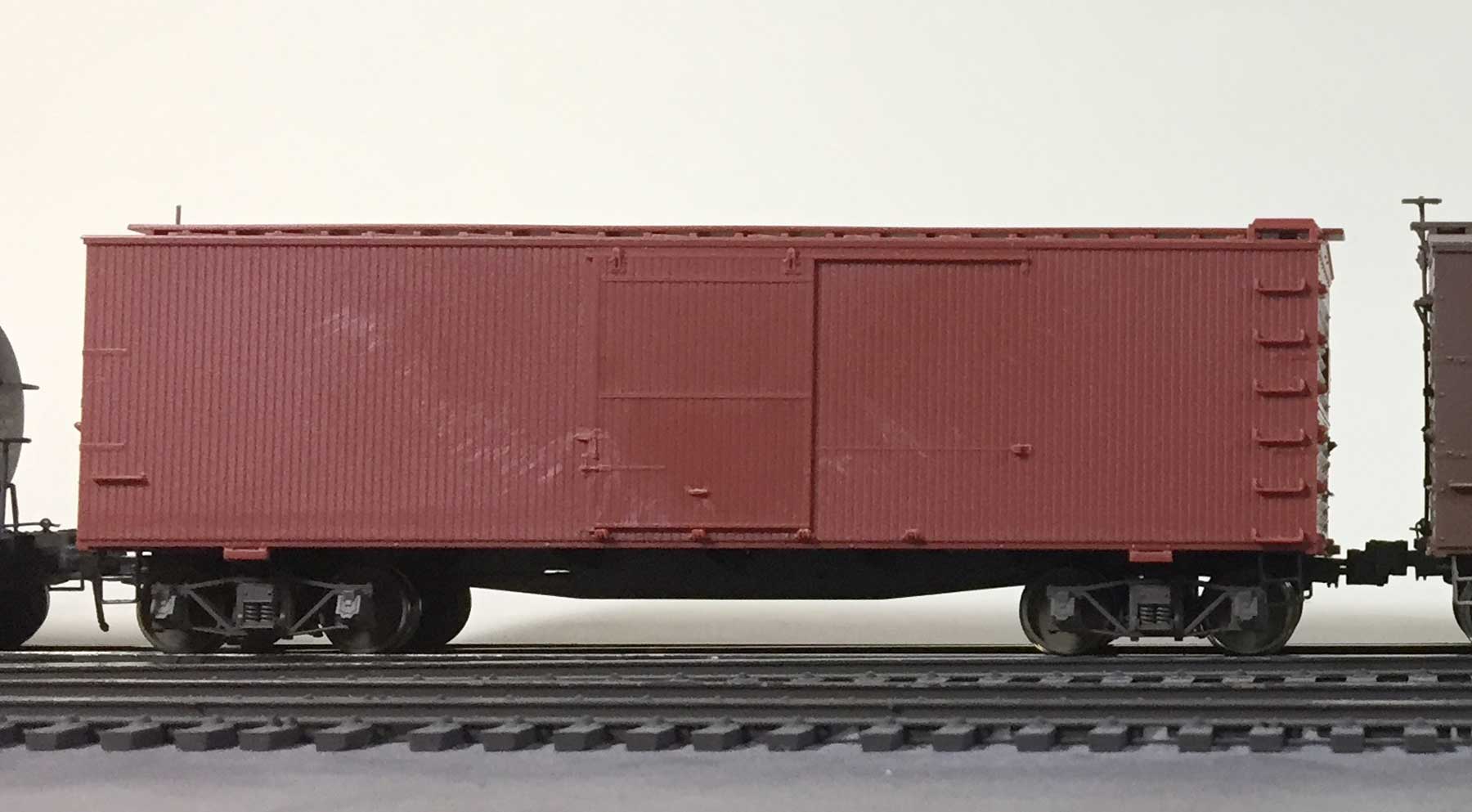
At this point, you probably think the coupler area looks funky. But the body casting has a part that covers this.

I use the Accurail Proto:HO scale couplers. The underframe casting has two smaller holes that are ready for the screws used to install these.

The Accurail Proto:HO scale couplers use a cover that reflects the prototype draft gear. The lid is not needed when installing these on the 36-foot box car kits. These couplers also have less play between coupled faces and reflect the prototype with a closer coupling than other products. They have worked well on many of my freight cars.
Now you are ready to assemble one or a dozen of the new Accurail 36-foot box car kits. Take your time with your first assembly and your will do a great job. Once you assemble four of these underframes, you can do this in a snap! Believe it or not, the above steps were done in an hour. That time includes setting up and taking the images with my iPhone. A PDF version of this tutorial is also available on the Accurail Prototype Data page on this blog for you to download and keep handy.
Thanks for dropping by and reading the blog. Share a comment in the section below. Please follow the instructions so your comment can be posted. All comments are reviewed and approved before they appear. To subscribe to this blog, enter your info for a comment and check the last box to notify of new posts by email. Please share the blog link with other model railroaders.
Thanks for this tutorial. It is wonderful that there is a coupler pocket cast on the end, something we do not see often. However, after installing the underframe it’s time to add more brake rigging to the ends of the car, install air hoses, cut levers and shave off the grabs and other items and replace them with wire ones to turn this into an outstanding model. Which probably will be the next tutorial…?
Thanks for your comments, Fred! I wanted this tutorial to just focus on building the underframe. Your suggestions are very good but mostly apply to car body details. I hope to update a future model by replacing the cast on grabs with Yarmouth etched metal ladders and wire grabs. It sounds like you have a solid upgrade outline ready to roll. I welcome blog submissions, Fred! 😉 – Eric
For the life of me I cannot figure out when and how I am supposed to install the trucks.
It’s easiest to do after the underframe details are installed and the couplers are installed. YMMV! – Eric
Great tutorial, Eric! This will come in handy for me. I’ve just ordered on of these on the assumption that somehow the Bullfrog Goldfield Railroad acquired something similar. It will be difficult for anyone to prove otherwise as there aren’t many records left.
I’ll probably get a D&RG and a NYC one eventually. It really looks like a great model. – Nevin
Eric,
The photos really clarify the Accurail instructions. A picture is worth 1000 words. This first look should greatly reduce the time to build for my first kit. The NKP car will be the first 36′ to join the NorthBayLines WWII freight fleet.
John Barry
Lovettsville, VA
Excellent clear, easy to follow tutorial, that both complements and honors an extremely fine model, not to mention the gifted person (and his company) who created and make it available for all of us.
Excellent. I await arrival, by sea mail, in a few months from an Aus hobby shop to here in Samar, Philippines.
Thanks for the as always highly useful and clearly presented tutorial. I am grateful that you provided it in PDF format to allow for easy reference in the future, an extremely thoughtful approach.
Eric, thanks for creating this tutorial! I used it to assemble three underframes in about one hour. The step-by-step instructions were clear and concise. I loved the close-up photos. These cars will soon be earning their keep on the Toledo & Ohio Central, circa 1918.
Doug Chapman
Montclair, VA